
Control System for Lasers at HiLASE
Introduction
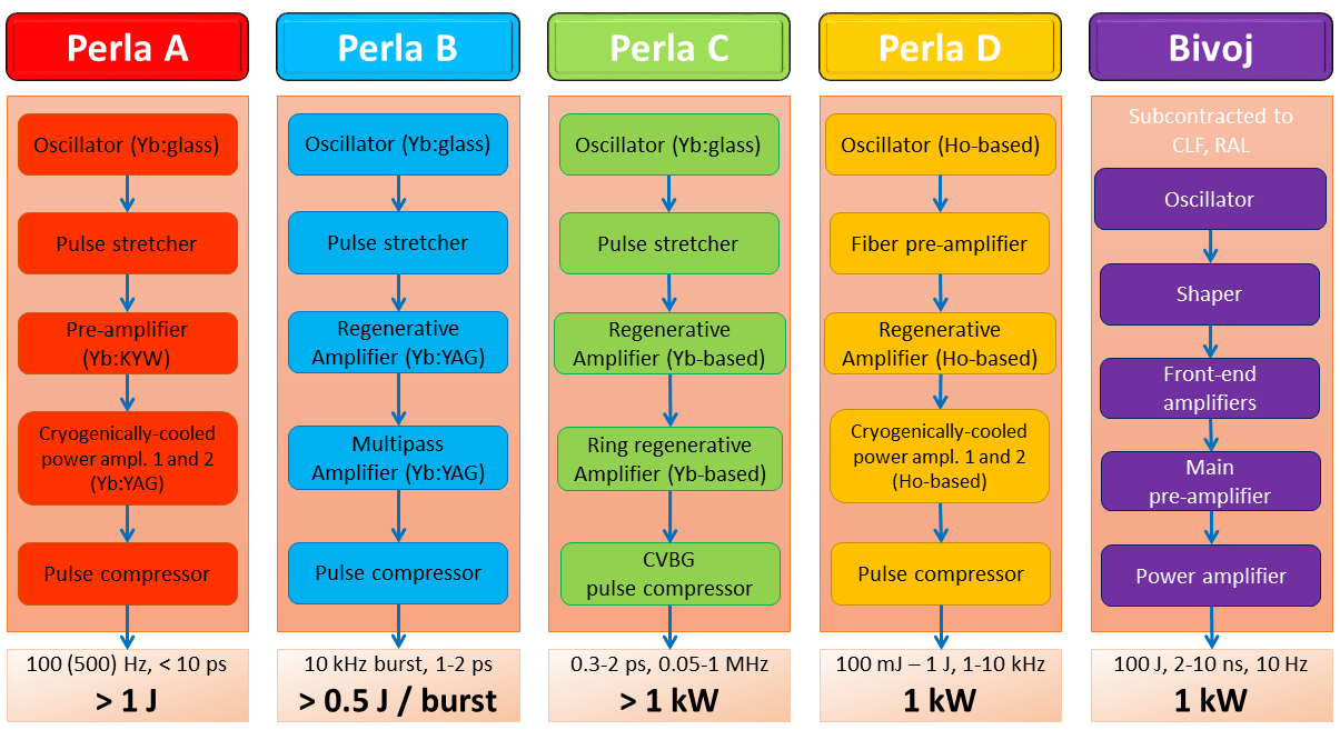
The R&D centre HiLASE (High average power pulsed LASErs) focuses on the development of advanced laser technologies. The main goal is to develop high-repetition rate, diode-pumped solid state laser (DPSSL) systems that may find use in research and high-tech industry. These systems have energies ranging from mJ to 100 J and repetition rates ranging from 10 Hz to 1 MHz. The systems are shown in Figure 1. Two major concepts within HiLASE are being explored: thin-disk laser amplifiers aiming for pulses with about a 2 ps width at repetition rates between 1 and 100 kHz, and multislab cryogenically cooled laser amplifiers that will generate nanosecond pulses with a 100 J pulse energy at a 10 Hz repetition rate.
While “Bivoj”, a nanosecond cryogenically-cooled multi-slab laser, is being developed in collaboration with the Central Laser Facility, Rutherford Appleton Laboratory (U.K.), and “Perla A” is subcontracted to Dausinger and Giesen GmbH, the thin-disk platforms “Perla B”, “Perla C” and the new “Perla D” are being developed in-house.

- Figure 1: Overview of the laser beamlines at the HiLASE (High average power pulsed LASErs) Centre, the targeted parameters are presented.
In-house Development
The development of ultrashort pulsed laser technology and laser components has been reported since 2015 [1, 2]. The most progressive development is the construction of the high repetition rate platform Perla C, which is important for the majority of industrial laser applications including lithography. Therefore, the development of the control system is focused on Perla C.
A generic control system architecture was chosen, so it can be applied to any of the Perla lasers, as an upgrade to the already existing control system of the Bivoj laser or to LBDS control system (Laser Beam Distribution System). The core of the architecture is a TwinCAT 3 real-time PLC which supports cycle times from 50 µs and multi-core CPUs. All digital and analog signals are connected to I/O terminals using the real-time industrial bus EtherCAT and passed to PLC programs. Communication between the PLC internal processes is provided by an ADS (Automation Device Specification) interface, which exchanges messages between the objects and allows the modules to be treated as independent devices. This ensures that all timecritical processes and functions will be managed in the designated order, moment and rate. The EtherCAT bus allows for a flexible and scalable topology, which is useful during development and even more during future extensions.
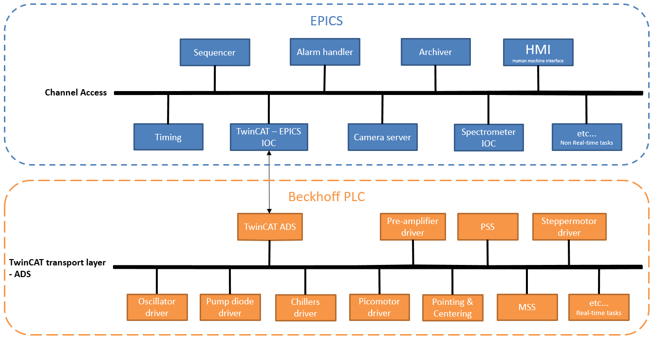
Although the EtherCAT terminals have numerous variations of I/O terminals, it would be very challenging and probably infeasible to connect all required laser and support devices to a real-time bus. Also, many software tasks, e.g. camera image processing or archiving, are not yet sufficiently sophisticated under the programming PLC standard IEC 61131-3. Therefore, an additional layer was designed and added to the control system architecture. The top layer is managed by EPICS. It is connected to the PLC via a TwinCAT IOC, a translator program which passes the EPICS channel access records to the ADS interface and vice versa. This top layer allows to connect to the control system any non-real-time tasks like archiver engine, alarm handler or human machine interface (HMI). The control system is depicted in Figure 2.

- Figure 2: Overall control system architecture.
Control System
The top layer of the control system is based on EPICS [3], which uses IOCs to communicate with field devices and can expose their parameters via two standard protocols: Channel Access and PV Access. IOCs are deployed on a Beckhoff IPC [4] running Windows 10. The Beckhoff IPC also includes a PLC. The PLC will later be used for the safety system, laser control, motion system, etc.
Timing System
The Timing System is used for the synchronization between the laser devices. The laser source outputs the trigger and the timing system delays the trigger for various devices, e.g., Pockels cell.
For timing and system synchronization, we use PCI delay generator cards. The cards support six outputs with delays from 50 ns to 429 s at a resolution of 25 ps.
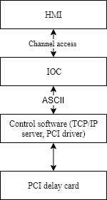
Control software runs on Windows as a desktop application and provides access to all configuration parameters of the card and calibration. It also includes the driver to talk with the card via the PCI bus. In addition, the control software provides a TCP/IP server. The communication with the TCP server is done via ASCII commands. This feature allows us to write EPICS device support to talk with the server. The software exposes card parameters as standard EPICS process variables (PVs) which can be monitored and updated via standard channel access clients as Control System Studio. The full communication stack is shown in Figure 3.

- Figure 3: Timing card integration.
EPICS device support is based on the StreamDevice module [5]. This is a natural solution as its main purpose is its write and read ASCII commands over serial interfaces. To achieve this, an EPICS database with a logic and protocol file had to be written.
Imaging
Laser size, shape and position are monitored with Allied vision GigE cameras [6]. Multiple cameras at appropriate locations are used. The acquired images are processed to extract a variety of desired image parameters.
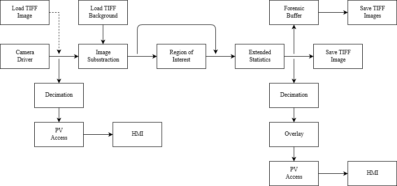
Implementation is based on the areaDetector [7] module which provides imaging support to the EPICS framework. The architecture is based on drivers, which talk to the hardware (cameras) and plugins. The plugins perform various operations on the acquired images. Images inside the module are represented as objects and are passed from one plugin (driver) to another as pointers, with all required attributes. This implementation is an efficient way to share the data between the plugins. The chain of plugins for Perla C is shown in Figure 4. Most of the plugins used are standard and only need to be configured. Some plugins needed additional functionality and were either developed from scratch or community versions of the plugins were upgraded. This includes: Image Decimator, Background Subtraction and Extended Statistics.
With the ADProsilica driver, the images are acquired from the detectors (cameras). For testing purposes (if a camera is not available), a static image can be loaded from a TIFF file.
The raw camera image can be seen on the HMI for initial inspection. A decimator is used to lower the frame rate, for lower network traffic. The images are forwarded to the PVA plugin which exposes the images on the network via the PV Access protocol. On the second (horizontal) branch, the image is forwarded to other plugins.
On the IOC, the first step for images is background subtraction. The plugin subtracts the selected image from the acquired images. The subtraction removes the background so that only the laser beam or changes to the laser beam are visible.
When the unwanted background is removed, the image is clipped to only display a region of interest. This is done with the ROI plugin from the community. If necessary, the ROI can be by-passed, if the user is interested in the whole area.
Additionally, statistics like centroid, intensity, FWHM and D4σ parameters can be calculated on the clipped image. Not all calculations are supported by the standard community statistics plugin, so it was extended.
For the last step images take three paths. Firstly, the images are displayed on the HMI. The display also includes an overlay which shows the center of the beam and beam size. Secondly, upon request the processed images can be saved on a local hard drive as TIFF files. Finally, the images are stored into a forensic buffer. The forensic buffer is a buffer containing the last configurable value of images.
The images get written to the disk, in case of failure, for further inspection.
Organizational Aspect
The collaboration between Cosylab and HiLASE is continuously improving. HiLASE drafts initial requirements. These are iterated with Cosylab. The HiLASE control system stakeholder and the Cosylab technical lead for development perform reviews. This allows for direct communication and ensures no information is lost. Requirements are finally approved by HiLASE. Part of the requirement document is forward looking and proposes how certain features will be tested. This gives a different perspective to certain requirements, and helps to clarify a definition.
During the design and development, any considerations, issues or ambiguity is addressed and resolved immediately. This keeps the development process smooth and expectations are aligned. A test plan is created by Cosylab and iterated with HiLASE. We learned it is important to include a user perspective into testing the software as the end users understand and use the application differently.
We use a two-stage acceptance process. The development within a “Work Package” is first tested at Cosylab using exactly the same hardware as the HiLASE target hardware. Any fixes and improvements are simplified with this methodology. Through an on-site visit, Cosylab experts and HiLASE execute test plan for final acceptance.

- Figure 4: Image processing chain.
References
[1] O. Novak et al., “Status of the high average power diodepumped solid state laser development at HiLASE”, Applied Sciences, 2015, 5.4: 637-665.
[2] M. Smrz et al., “Advances in High-Power, Ultrashort Pulse DPSSL Technologies at HiLASE”, Applied Sciences, 2017, 7.10: 1016.
[3] Experimental Physics and Industrial Control System, https://epics.anl.gov/
[4] BECKHOFF New Automation Technology, https://www.beckhoff.com/IPC/
[5] StreamDevice 2, http://epics.web.psi.ch/software/streamdevice/
[6] Machine Vision Cameras Selector – Allied Vision, https://www.alliedvision.com/en/products/cameras.html
[7] areaDetector: EPICS software for area detectors, https://cars9.uchicago.edu/software/epics/areaDetector.html
10th Int. Particle Accelerator Conf., IPAC2019, Melbourne, Australia.
JACoW Publishing, ISBN: 978–3–95450–208–0
DOI: 10.18429/JACoW-IPAC2019-WEPGW007
Content from this work may be used under the terms of the CC BY 3.0 licence ( © 2019). Any distribution of this work must maintain attribution to the author(s), title of the work, publisher, and DOI.